Wednesday, March 16, 2016

◙ UPDATE: 3D Printing a Sam Yang Recluse .357 Bipod Barrel Mount ◙

Hi folks,

So you might remember I 3D printed myself a Bipod Barrel Mount earlier for my Sam Yang Recluse .358 HPA Air rifle. And I have had some time to test it out now a bit.

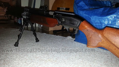
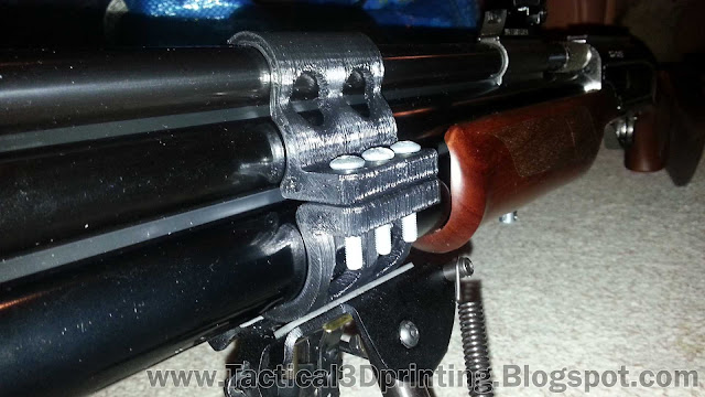
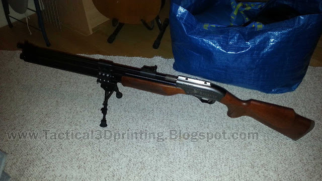
Updated 3D Printed Bipod Mount
And like I said in my earlier post I might make a new bottom part for the barrel mount.

If you want to know the beginning of this 3D Printed HPA story.

Then you can check out my earlier post and find out all the details here of my 3D printed bipod barrel mount for the .358 Sam Yang Recluse HPA air rifle

3D-Printing-Sam-Yang-Recluse-357-Bipod-Barrel-Mount
Old 3D design of the Bipod Mount that broke
Old Barrel Mounted Bottom Part 3D design that broke the plastic "swivel stud"
The reason for the change was that the original design for the "swivel stud" attachment was a weak point. And I already broke it once when I attached the bipod and started to tighten the screw for the swivel stud and it broke the little hole on the bottom of the part. It was my fault and I over tightened the screw by mistake, but even so it's that plastic part that supposed to do the job of the swivel stud and hold the bipod in place that's the weak link.

Well I did design a new bottom part so I could 3D print it, however I have not had the time to 3D print the part. Print time for the new design is about 2 hours, and I usually don't print overnight. So I simply have not had the time lately to mess around with the printer.

However I had the old part sitting on the heating bed of my 3D printer and I figured now is the time to try and fix this. I can still reuse the old broken bottom part. My plan was to simply reshape the old part, cut away what was left of the broken plastic and then drill a hole and replace the "swivel stud" with a screw instead.

Cut away the "swivel stud" and drilled a hole in the center for the screw
The first thing to do was to cut away what was left of the broken plastic, I used the grinder to cut off what was left and smoothed out the plastic so I could center a hole in the middle of the part. I needed the hole drilled to be level and straight so I used the drill press to make a smaller 4mm hole first and then I used a 5mm drill to finish the drilling operation. 

I use the same 5mm screws that I already used to attach the upper and lower parts of the bipod mount. And of course I dropped the first screw on the floor I had with me when doing the drilling and it's now missing in action. But that's OK, I have a bunch of these 5mm screws.

Countersunk hole for the 5mm screw
I needed to countersink the 5mm screw into the plastic to make the bipod mount fit like it should. I found an old 10mm end mill cutter over at the old lathe that did the job. I used a 11mm drill to make the first cut, so I could get it to center the end mill. And then went ahead and made the countersunk hole. I also used the drill bit to take some of the edges off once done.

Finished Updated Bottom Part with the bipod attached
So here is the finished result, I had to use a few extra washers on the bottom of the bipod to get it right but other than that it turned out really good. It feels really solid now and I doubt it will break again. The one downside in doing it this way is that it's not much of a swivel bipod anymore. But there is a little bit movement in the bipod and it's legs to allow for small adjustments.

So yeah, I guess I need to test this out a bit more now and see how it works out. But first impressions are good for this rather quick fix.

Monday, February 1, 2016

◙ 3D Printing a Rifle Stabilizer ◙

Hi folks,

So yesterday I was in the chat over at GTA and and the guys over there were discussing a neat little product. I thought I could 3D print that, and we had ideas going back and forth. Check out the chat at www.gatewaytoairguns.org and the product in question is at http://ultimatesniper.com they have for sale called a Rifle Stabilizer.

Rifle Stabilizer
Rifle Stabilizer by ultimatesniper.com
They explain it like this:

"Competitive high-powered rifle shooters have long realized that the most accurate shooting requires steadiness from skeletal support, while also alleviating the tremors of respiration and heartbeat. The Rifle Stabilizer's simple but sophisticated design addresses all three."

So the discussion in the chat was how could one make something similar. Really how hard could it be, it's a stick right?

PVC pipe or something out of aluminium would be ideal, however my concern was that PVC or similar thin plastic pipe would bend and not be able to hold the rifle steady.

Well it just so happened that I found a plastic handle and thought I could try and 3D print the thing. The length of the handle was 18 inch, that's around 46 cm and I figured that would be enough and the end was already threaded.

3D Printing a Rifle Stabilizer Drawing And Print 1
The other end of the handle I figured I could use to attach it to a belt with a hook or something similar.

3D Printing a Rifle Stabilizer Drawing And Print 2
Now the tricky part of this 3D print would be to get the threads right. And also have the right tolerances so that the 3D printed part would actually screw on once finished. And I'll explain more about this further on.

So off to the computer and do some 3D modeling!

My go to modeling software for 3D printing have always been Soildworks. It's such a powerful program, and I can not speak highly enough of it. Even though I have been using Solidworks since 2004 it's one of those softwares that only have changed slightly over the years. So even if you picked up an old copy from 2004 and had to jump over to the new 2016 version you would not feel lost. And seriously you would be able to do all the work needed in the 2004 version if it came to that.

3D Printing a Rifle Stabilizer CAD Drawing Part Solidworks 1
So this is the part I came up with to fit the threaded handle I found. I measured I would need a 2 inch or around 52mm rest for my Sam Yang Recluse Air Rifle I'm using. And the threaded part of the handle measured in at around 20mm or 0.8 inch.

3D Printing a Rifle Stabilizer CAD Drawing Part Solidworks Cross Section
Here you can see a cross section of the part with the threads. I have found that plastic parts can have some weird looking threads and this handle is no exception. I measured the pitch to 4.5mm and the cut was done with a 3mm "ball" at the appropriate distance to get the desired thread cut. I also wanted to print without any support material so that's why there is a chamfer at the bottom of the thread. Filament 3D printers don't print well in open air!

3D Printing a Rifle Stabilizer CAD Drawing Part Solidworks Cross Section 2
So this is where it starts to get tricky. I know from experience with 3D printing that you won't get parts that are 100% accurate to what you put in the modeling software. And the reason for this is Thermal Expansion.

The plastic I print with is usually ABS (the same plastic Legos are made from) and the temperature the plastic comes out of the nozzle is around 220c. It depends on the plastic but usually around 220c when it gets put down on the printed part.

Anything that cools down starts to shrink and a plastic that cools from 220c to 20c is no exception. And that's why it gets a bit tricky. But as you 3D print more you learn how to compensate for this and the more you print the better you become I guess.

Trail and error with 3D Printing!


So is there a solution to the tricky part? 

Yes! 
  1. You can go and buy a 100.000 dollar 3D printer and be done with it
  2. Or you can do test prints before you print the whole part!
3D Printing a Rifle Stabilizer Drawing And Print 3
I got close this time, really close on the first try. I did a 10mm test print of the threaded section of the part to test and see how the threads would fit and it screwed on. 

The part was a little bit tight on the threads and I had to work it to get it to screw on. I felt that there was a little bit too much friction so I decided to make the thread cut 0.05mm larger and also 0.10mm larger overall.


Rostock Max in action
3D Printing a Rifle Stabilizer - Rostock Max White ABS 1
Here's my Rostock Max in action 3D printing the part. It only takes a few minutes to print a test part and make the adjustments, so once that have been done it's fingers crossed that the threads would come out as predicted. Of course I could have printed yet another test part to test if the threads would actually work but hey, I've been 3D printing for about 3 years now with this Rostock Max so I'm getting pretty confident.

The printer is a pretty stock Rostock Max with ramps running a bit higher voltage to help speed up the heating time of the heater bed. And I also have added cooling fans for the bed and 3d printer electronics and a heat shield for the extruder to keep the reflective heat from the nozzle away from the printed part.


Rostock Max in action almost done
3D Printing a Rifle Stabilizer - Rostock Max White ABS 2
Almost done now, only about 50 more layers to go. Print time on this part was around 40 min. The settings I normally use for 3D printed parts that I want to finish quick are printed in 0.30mm layer height. This is a good compromise between speed and final quality of the printed part. Think about it, if I had used 0.15mm layer height the print time would have been 80 min instead.

I could have run a bit faster speeds with this white ABS plastic, but I find that 40mm/s with 55mm/s 90% infill is the sweet spot when I print with 222c extruder temp and 0.30mm layers. It gives you strong parts with good layer bonding. I have been using Cura 14 for slicing the last couple of months now and I find that it works pretty well, but I did have some issues with the latest release of Cura so I will stick with the one that works best for me for now.

All done!


3D Printing a Rifle Stabilizer Finished Part 1
So here is the finished part, I only did a bit of cleaning on the part to take off the brim lines (this helps the printed part to stick to the bed when printing so they don't go flying off on you). I was a bit lazy and I used a grinder to put a chamfer on the end. It's quick and it turns out better than using a file or knife.

This picture shows how the threads turned out, and it looks pretty good for a 0.30mm layer height.. 

So did it work?


3D Printing a Rifle Stabilizer Finished Part 2

Here it is, the finished 3D printed Rifle Stabilizer. And yes the part screwed on really nice and it turned out really well. And it's the right size for my Recluse.

So did it really work as a Rifle Stabilizer?

Well no, actually when I gave it a try the overall length is a bit too short for me and 18 inches is not enough for me to get a level shoot with my rifle. It would work if I was aiming down a slope, but it's too short when I have it resting on my hip like in the picture. I would have to add a few more inches to the handle for it to work like it should and give me a level shoot.

But that's the thing with this Rifle Stabilizer, it needs to be adjustable in length. So now I only need to figure out the best way to get it adjustable. Or perhaps it could be done with a belt that you have around your waist. Either way it's a proof of concept and I can also confirm that a PVC pipe would be rigid enough to use if someone can figure out a way to get it adjustable.

Comment, Share, like, Subscribe, Thumbs up, or Thumbs down if you hate it!

If you like this also check out my recent post

Friday, January 29, 2016

◙ 3D Printing a Sam Yang Recluse .357 Bipod Barrel Mount ◙

Hello everyone!

This is a little 3D Printed project of mine I finished a few weeks ago for my new Sam Yang Recluse .357 cal Air Rifle.

This is a long post, with lots of pictures. Share, like, subscribe, comment if you like it and thumbs down dislike if you hate it.

If you are familiar with the other Korean Sam Yang big bore air rifles like the .457 cal 909 Light Hunter or the big one the .50 cal Dragon Claw you know that these types of PCP air rifles are a bit on the heavy side.

Sam Yang 357 Recluse 2016 - 3D Printed Barrel Bipod Mount
Especially now since they have come out with the 500cc dual-tank models. The .357 Recluse weights in at 8.5 lbs. While the more compact and small caliber .22 and .25 cal Sam Yang Sumatra Carbine weights in at around 6 lbs. Sure it's not that heavy but I like to sit down and shoot mine from a rest and also do some free hand shooting.

So I figured I'll just slap on a swivel bipod and be done with it, however due to the design of the Sam Yang air rifles I found that for my taste the bipod came a little bit too far back. 

And also it made it difficult to do free hand shooting with having the swivel bipod mounted in that location seen here in this picture.

Now that picture show you the old single-tank model of the Dragon Claw and that could work just fine. But I also found that with the new 500cc dual-tube versions they are more heavy in the front. So often if I wasn't careful when I picked up mine it would just tip over and bang the tube in the floor.. Too much weight in the front and the bipod located too far back to balance the rifle.

Well what do you have a 3D printer for if not to fix things right!

So I needed to mount the bipod to the barrel, however being an air rifle and also a dual-tank PCP air rifle there isn't really any bipods that allow you to do that with this setup. I figured I needed to make something strong that would hold some abuse, and also be slim enough that I still could use the iron sight on the rifle if needed.

Luckily the iron sights on the Sam Yang air rifles are mounted very high of the barrel so having something mounted around the barrel would not distract or block the sight. Another thing was I didn't want to pull anything apart from the rifle when mounting the bipod, and if the mount should brake it needed to be able to come off with ease.

Off to Solidworks and do some CAD Design!


Sam Yang 357 Barrel Bipod Mount v5 top Solidworks CAD
So the first thing I do when 3D printing is determine the exact dimensions. And what I mean by that is in this case I wanted the top part seen in the picture to have a tight fit to the barrel and snap into place when fitting. There needed to be enough strength to the part that it would not brake in use, but also be flexible enough to be able to go over the tubes. The design seen here is version number 5.

3D printing is not an easy thing, really. It's just like any form of practice, it's an art and it takes some time to master 3D printing. These air rifle parts needed to be strong so ABS plastic is what needs to be used, if not then Nylon is the preferred material. Both materials have different properties and uses and they also print different.

To get the right tolerances on the top part I designed 5 parts and printed 3 of them to check if they where fitting like they should on the barrel. Now I didn't finish the prints because I only needed the outline of the barrel printed, and that took only a few layers to get, so once I was happy with how it looked and tweaked the design I went ahead and printed the final fifth version and it snapped on just like I planned.

Sam Yang 357 Barrel Bipod Mount v5 bottom Solidworks CAD
The bottom tube is the big one and this is the part that needed to both snap on and fit snug to the tube and attach to the top part. And also finally attach to the swivel bipod.

I made the decision to attach the bipod to the bottom with the same configuration swivel type stud and I figured it would hold if I printed this in one piece.

Sam Yang 357 Barrel Bipod Mount v5 Assembly Solidworks CAD
This is the final assembly in Solidworks and you can see that the holes line right up, because I measured twice! I made the holes on the top part big enough that I could fit some 5mm bolts I had, and the holes in the bottom part I made smaller so I could use a thread tap. This way I didn't need to use any nuts and the ABS plastic is plenty strong to hold threads.


Sam Yang 357 Barrel Bipod Mount v5 Assembly Side Solidworks CAD
However I went ahead and added some space to fit nuts if it so happened that the threads in the plastic would fail sometime in the future.. Or if I messed up the delicate procedure of tapping plastic!

Here it is! Finally 3D Printed Bipod Mount!


Sam Yang 357 Recluse 2016 - 3D Printed Barrel Bipod Mount v5 2
Well I didn't mess anything up, and what it looked like on the computer is how it turned out in real life also! And I managed to tap the threads in the holes without problems for the 5mm bolts that are holding it together.


Sam Yang 357 Recluse 2016 - 3D Printed Barrel Bipod Mount v5 1
Looks nice does it not, both parts fits nice and snapped over the barrel and tubes. So there is no need to take anything off the rifle to remove the mount. Well I could probably have only used 4 bolts to hold things in place, and not the 6 bolts like how it was designed to begin with. However I like to think that 6 bolts spreads the load a bit more even over the barrel and tubes so it's less a strain on the ABS plastic that way.


Sam Yang 357 Recluse 2016 - 3D Printed Barrel Bipod Mount v5 3
Now for you that already have been 3D printing for a while and want some details, these two parts where printed separately. I didn't use any support material on the parts to print these. And I often design and print parts so I don't need to use any support material because it always takes some time to remove afterwards.

I find it that if I can make a part without support material it turns out looking cleaner.
Sam Yang 357 Recluse 2016 - 3D Printed Barrel Bipod Mount v5 4
You might notice that the bolts used are a bit on the longer side, almost twice the length needed. But at the time these where the bolts I had handy at the time, and I guess I could shorten them.. But it just takes so much time to screw these in and out by hand, the thread pitch is 0.75mm!


Sam Yang 357 Recluse 2016 - 3D Printed Barrel Bipod Mount v5 5
This Sam Yang Recluse is not front heavy anymore! Now I can pick it up and not have to worry about it tipping over. And I can do free hand shooting too without having the bipod in the way!


Sam Yang 357 Recluse 2016 - 3D Printed Barrel Bipod Mount v5 8
The bipod mount is also slim enough over the barrel that it won't get in the way of the iron sights when aiming down the sight. And you would need to have a really big scope on there to even get close to it. But the thing is, I can also slide the bipod mount all the way to the front if I ever needed to. Just slightly undo the 6 bolts and the bipod and mount slides back and forth.


Sam Yang 357 Recluse 2016 - 3D Printed Barrel Bipod Mount v5 6
Ok so, to get back to the 3D printing settings I used. The 3D Printer is the Rostock Max running ramps hardware custom 3D printed bracket for extruder heat shield that is used when printing ABS and cooling fans to keep temperature under control. Cura is my preferred slicer.

EZstruder is a direct drive extruder and for me to get good retraction on the prints I run around 800mm/s and 10-12mm for ABS with the stock Rostock Max 0.5mm nozzle. Remember this is a direct drive extruder, so you need to run the extruder stepper motor faster and longer than a geared one. But not too fast or you start to grind the filament. And make sure you run cooling fans on the board or the extruder stepper motor will start to skip and loose steps.

I think I used 0.30mm layer height on this 3D print, and 90% infill. I usually need 30 brim lines to make sure the part sticks to the bed good. I find that 0.30mm layer height gives decent looking 3D prints and it also more importantly cuts down on the overall print time. However for smaller parts I normally do 0.15mm if I need that extra detail. Extruder temp around 220c and bed temp around 70c. The bed I use is a mirror on top of a machined 5mm aluminium plate that's sitting on the Rostock heater platform. To get parts to stick good to a mirror or glas surface I personally use wood glue that's diluted with water. A few coats on the mirror and the parts stick well, however it is critical to have the right height on the first layer. Even 0.05mm difference here is what can cause the print not to stick good on the bed and you start to get corners lifting or the whole part coming loose. I find that for me I get better finish if I only run around 45mm/s for the inner and outer shell speed and I found that the black Chinese ABS plastic I have right now didn't like anything over 65mm/s on the infill or it would start to make holes in the infill.

Print time for both parts I estimated to around 2-3 Hours, but I printed one part at a time and also did some design while the parts where printing so not to bad. But there is not really anything you can do about the print time. If you want the print to look nice and not fail mid way etc. It's always best to stay with what you know works and not try and rush things.

Sam Yang 357 Recluse 2016 - 3D Printed Barrel Bipod Mount v5 7
So in the end I probably ended up spending a week on the design and printing, I recon about 10 hours to get to this point with the bipod mount. Did I mention it broke? Well it did, I attached the bipod and started to tighten the screw for the swivel stud and it broke the little hole on the bottom of the part. That plastic part that supposed to do the job of the swivel stud and hold the bipod in place.

On closer examination I found that the bottom printed part was a bit to large for it to go down into the hole in the bipod. So I had to carve out a bit on the sides of the "plastic swivel stud" so that it would fit and then it all worked like it should.. But it's nothing like it when you spend hours printing something and it starts to brake before you even get it assembled.. But it turned out OK this time.

So if there is anything that I would think would brake on this 3D printed bipod mount then it's that little plastic swivel stud. So in the future if that happens I might just make a new bottom part with the plastic swivel stud replaced with a real swivel stud and have that threaded into the plastic instead. Oh and I might just shorten the bolts while I'm at it.

Thanks, Share, like, subscribe, comment if you like it and thumbs down, dislike if you hate it.


UPDATE: New Bipod Barrel Mount Part Fixed

This is the updated bottom part for the bipod that I made as a quick fix
◙ UPDATE: 3D Printing a Sam Yang Recluse .357 Bipod Barrel Mount ◙


You may also like


◙ 3D Printing a Rifle Stabilizer ◙ 

Do you have a steady hand?